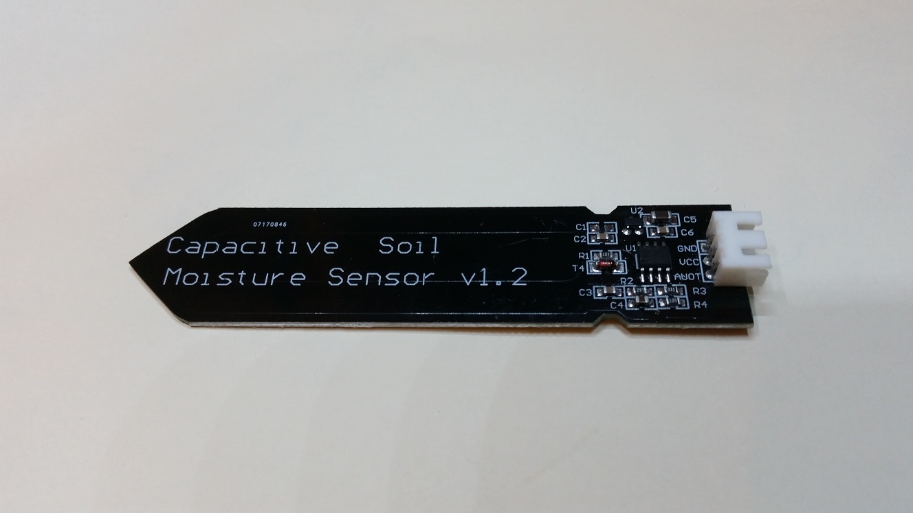
capacitive soil moisture sensor (capsense)
 As part of our
Greenfinger
project, we required some way to measure soil moisture.
Not long into that part of the project, we found something was very amiss with our chosen sensor.
After publishing a Youtube video on the subject,
we received several interesting comments and some equally intereresting new observations.
Feeling the need to keep our viewers updated and to share their new information,
we created these, the CapSense pages.
The youtube video
After finding and fixing the fault with the sensor,
we published a Youtube video showing how we found and fixed the fault.
If you have not seen it, but want to, then dare to click on the link below.
This will open a new tab for you to view the video in.
Using this link has the advantage of you being able to see the comments that viewers have posted.
They include other faults which have been found when using this sensor.
>>The video<<
The video, but not Youtube
This is the same video, but you don't get shunted off to Youtube to see it.
After the video
After we published the video,
a few viewers began commenting that, in some cases, our solution fixed their problem.
In other cases, it did not.
Some viewers commented that they had received several of these from the same seller,
some of them worked, some of them didn't.
Our remedy corrected some of the faulty ones, some it did not.
Here we will go through some of the problems.
Unfortunately, we don't have all the variations of this unit to test.
If anybody wants to donate faulty examples for us to dissect,
please leave a comment on the Youtube video.
Not all Soil Moisture Sensors are created equal.
The ones we have are marked v1.2. We have not seen a v1.1.
Even v1.2 units look similar, but there are slight variations.
Presumably copied and produced by several manufacturers.
It seems some bugs have crept in during this copying process.
Problem #1
The sensor responds slowly or SO slowly it appears not to respond at all.
Readings are around 600 - 900.
Cause : This is almost certainly caused by the 1 Mega-Ohm resistor not being connected at one end.
The video below shows an in-depth explanation of this.
If this is too much information, skip to the next section for a quick fix.
Solution #1


Referring to the images on the left (click for a close up).
Either will do the same job, i.e. grounding R4 as it should be.
Note #1: The boards are usually coated with black etch-resist so the traces would not normally be visible.
We have removed the etch-resist for clarity.
Looking closely, you will be able to see the traces raised from the board.
Note #2: This operation is performed on the component side of the board.
We have removed the components for clairty.
Note #3: The resistor is marked as R4 on the board.
The diagrams we have seen state that it is R1. See our revised diagram below.
The fix: Scrape off the etch-resist in the area shown and solder a small wire link in place.
Problem #2
The sensor appears not to work at all, constantly showing a zero reading.
Cause : One of our Youtube viewers bought several devices and found they were fitted with
NE555 chips instead of TLC555 chips.
Unfortunately he returned them before I could scrounge one for surgery.
The NE555 requires a minimum 4.5 volts supply. The TLC 555 requires a minimum 2 volts.
(according to Texas Instruments datasheets).
The voltage regulator on the sensor board is said to be a XC6206P302 which outputs 3.0 volts.
A 3 volt regulator cannot supply a 5 volt NE555.
Update July 2020:
One visitor to this site said that he had a version with a NE555 fitted.
He also noted that his sensor was fitted with a 5 volt regulator.
That's all very well but then the regulator needs an input greater than 5 volts.
Driving it from the 5 volt rail of an Arduino for instance, will not supply enough power.
Thanks Richard for that info.
Solution #2

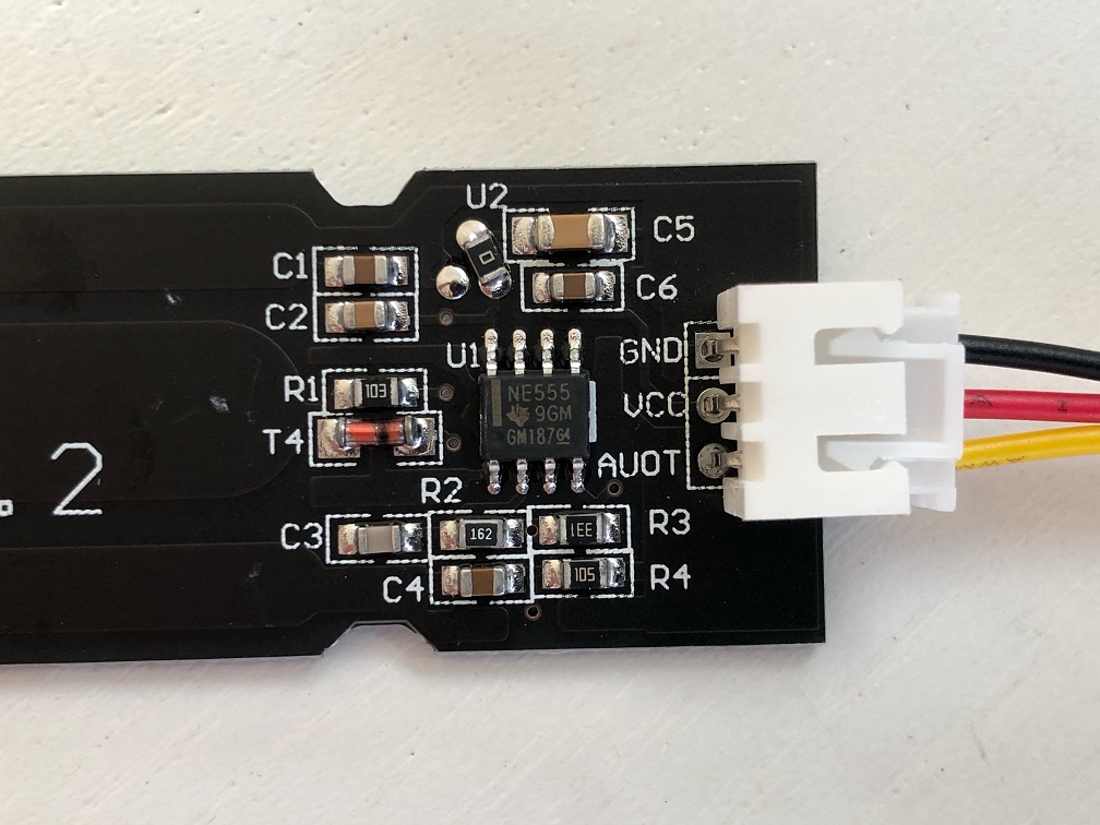
 Check that U1, the 8 pin chip on the board is in fact a NE555 type.
The fix: Remove the regulator and solder a small wire link in place.
Referring to the image top left (click for a close up).
Locate and remove the voltage regulator U2.
It is a small, square device with 3 pins.
Referring to the image bottom left (click for a close up).
Solder a short wire between pins 2 and 3.
With the board oriented the same as in the image,
The pins would be top middle and bottom right.
Note #1: Take great care to connect only those two pins together.
Otherwise you may let some smoke out.
Note #2: If you are careful and have good soldering skills,
you can add the link without removing U2.
Note #3: The sensor must now be supplied with a regulated 5 volts supply.
The output will also be between 0 and 5 volts.
O.K. for an Arduino, but make sure your intended processor is 5 volt tolerant.
Another visitor e-mailed me with some fascinating new information.
Here's what he said:
"Hi Stewart,
Thank you for your YouTube videos and your page on the various issues with the capacitive moisture sensor. I was pulling my hair out for ages trying to work out what was going on.
I wanted to share the specific variant that I was having issues with just in case it's of interest. I have the same issue as the person who posted on your video - I've got a NE555 chip on the sensors I have. But interestingly the manufacturer has already made the fix by putting a 0 ohm resistor in place of the voltage regulator:

The issue I have is that I'm trying to use it with a Nano IoT which only accepts 3.3v inputs and the seller stated the original intended spec i.e. max 3v output. I tried powering it with 3.3v which obviously didn't work, tried 5v and the analogue signal jumped to 1023. Luckily I guessed what might have happened and pulled the jumper out before it damaged the board.
Anyway, thanks again for your work documenting these things. I'm going to have a play with trying to get this one working at a good range for the Nano IoT.
Thanks,
Ben"
Thanks To Ben Morfoot for taking the time to provide us with this new info.
Looking closely at the image Ben supplied, it looks like the ground trace to R4 is also broken. It seems that this revision will also require the wire link mod for correct operation.
In a later e-mail, Ben confirmed this to be the case.
Problem #3
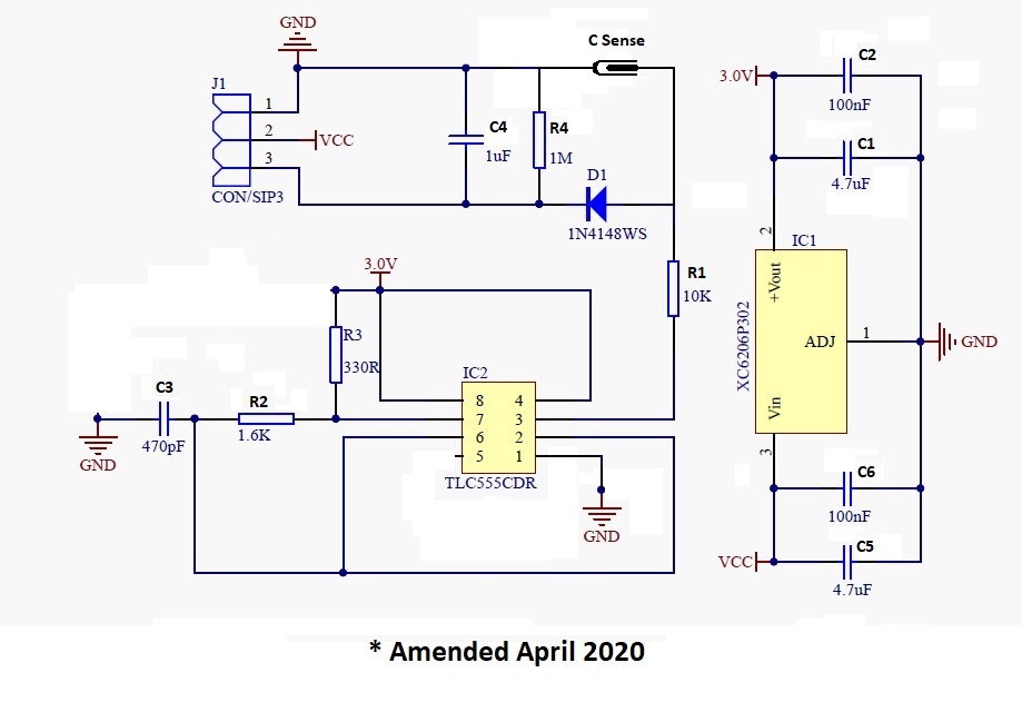
 The Circuit diagram problem.
Whilst trying to find out why our sensor was not working,
we downloaded many variants of what was claimed to be the correct schematic diagram.
The first clue that none of those were correct was that the offending resistor is marked R1 on the diagram,
yet the only 1 Mega-Ohm resistor on the board is marked as R4.
The second clue was there are 8 capacitors on the diagrams,
but only 6 on the board.
Solution #3
 Use the schematic diagram shown here.
After we removed the components and etch-resist from our donor board,
We were better able to see which components were which and what went where.
We have amended the diagaram accordingly.
