Getting real results


 Here we will create an example sketch which uses our learning from the previous few pages, using Arduino Uno.
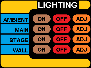
We will use all of the parts of the TFT to simulate a switch for controlling some lights,
using the Star Trek style LCARS interface, with a Seeed Studio 2.8 TFT Touch Shield V2.0.
Later, we will make this a part of our real-world MQTT automation project.
Right-click on these images to download them. The first one will form the main menu in our example.
Download the additional images.
We will use these to overlay the main menu bitmap, depending on button presses.
These are smaller because we will only need to change parts of the screen. This will save time redrawing.
After dowloading all of them (there should be 9 in total) copy them to the root of your Micro SD card.
Insert it into the TFT card slot.
We should be ready to rumble.
Laying the Foundations


I could calibrate the screen in software but to me, right now, it's not important.
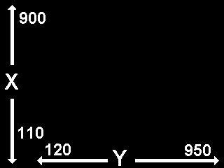
Un-calibrated, the touch data returned seems to be similar to the image to the left.
However, I am only interested in sensing touch from a small portion of the screen.
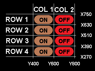
The area where the eight ON / OFF buttons reside. In actual fact, only about one third of the total screen area.
In code, I will therefore delineate that area into rows and columns, as shown in the image to the left.
So, for instance:
if (X > 390 AND X < 510) AND (Y > 600 AND Y < 800)
I know that the button in ROW 3, COL 2, was pressed.
Time to code
 OK. Example code below.
Click here to download
Use the serial monitor for some debugging.
#include <TouchScreen.h>
#include <Adafruit_GFX.h>
#include <Adafruit_ILI9341.h>
#include <SPI.h>
#include <SD.h>
// For the Adafruit shield, these are the default.
#define TFT_DC 6
#define TFT_CS 5
#define SD_CS 4
// Use hardware SPI (on Uno, #13, #12, #11) and the above for CS/DC
Adafruit_ILI9341 tft = Adafruit_ILI9341(TFT_CS, TFT_DC);
#define YP A2 // must be an analog pin, use "An" notation!
#define XM A1 // must be an analog pin, use "An" notation!
#define YM A0 // can be a digital pin
#define XP A3 // can be a digital pin
TouchScreen ts = TouchScreen(XP, YP, XM, YM, 300);
uint8_t giOldSwitchState = 0b00000000; // we have 8 switches !!! Switches are NOT the same as buttons
uint8_t giNewSwitchState = 0b00000000; // we will only use 4 in this demo
void setup() {
Serial.begin(9600);
Serial.println("MQTT_Touchscreen demo.");
tft.begin();
// yield();
Serial.print("Initializing SD card...");
if (!SD.begin(SD_CS)) {
Serial.println("failed!");
}
Serial.println("OK!");
tft.setRotation(3); // we want landscape
//tft.fillScreen(ILI9341_BLACK);
bmpDraw("menu1.bmp", 0, 0);
}
//Main program loop.
void loop(void)
{
uint8_t button = getButtonPress();
if (button) // Anyone touching the screen?
{
Serial.print("Button = "); Serial.println(button);
// we will use bitwise operations to manipulate our switches
// we have up to 8 switches, but we will use only the first 4.
// Switches are NOT the same as buttons.
// Pressing an ON button on the screen, activates a corresponding switch
// Pressing an OFF button on the screen, de-activates a corresponding switch
// Demonstrating this with many if statements, may make it easier to follow.
// There are more efficient ways to do it !!!!!
if(button == 1)
{
giNewSwitchState = giNewSwitchState | 0b10000000;
}
if(button == 2)
{
if(giNewSwitchState & 0b10000000) // Only switch off if it is on
{
giNewSwitchState = giNewSwitchState ^ 0b10000000;
}
}
if(button == 3)
{
giNewSwitchState = giNewSwitchState | 0b01000000;
}
if(button == 4)
{
if(giNewSwitchState & 0b01000000) // Only switch off if it is on
{
giNewSwitchState = giNewSwitchState ^ 0b01000000;
}
}
if(button == 5)
{
giNewSwitchState = giNewSwitchState | 0b00100000;
}
if(button == 6)
{
if(giNewSwitchState & 0b00100000) // Only switch off if it is on
{
giNewSwitchState = giNewSwitchState ^ 0b00100000;
}
}
if(button == 7)
{
giNewSwitchState = giNewSwitchState | 0b00010000;
}
if(button == 8)
{
if(giNewSwitchState & 0b00010000) // Only switch off if it is on
{
giNewSwitchState = giNewSwitchState ^ 0b00010000;
}
}
Serial.print("Old switch = "); Serial.print(giOldSwitchState);
Serial.print(", New switch = "); Serial.println(giNewSwitchState);
// We only re-draw screen if something changed
if(giNewSwitchState != giOldSwitchState)
{
//which part of the screen do we have to re-draw?
// If first switch went from OFF to ON
if(((giNewSwitchState & 0b10000000) == 128) && ((giOldSwitchState & 0b10000000) == 0))
{
bmpDraw("menu111.bmp", 0, 48);
}
// If first switch went from ON to OFF
if(((giNewSwitchState & 0b10000000) == 0) && ((giOldSwitchState & 0b10000000) == 128))
{
bmpDraw("menu110.bmp", 0, 48);
}
// If second switch went from OFF to ON
if(((giNewSwitchState & 0b01000000) == 64) && ((giOldSwitchState & 0b01000000) == 0))
{
bmpDraw("menu121.bmp", 0, 84);
}
// If second went from ON to OFF
if(((giNewSwitchState & 0b01000000) == 0) && ((giOldSwitchState & 0b01000000) == 64))
{
bmpDraw("menu120.bmp", 0, 84);
}
// If third switch went from OFF to ON
if(((giNewSwitchState & 0b00100000) == 32) && ((giOldSwitchState & 0b00100000) == 0))
{
bmpDraw("menu131.bmp", 0, 120);
}
// If third went from ON to OFF
if(((giNewSwitchState & 0b00100000) == 0) && ((giOldSwitchState & 0b00100000) == 32))
{
bmpDraw("menu130.bmp", 0, 120);
}
// If fourth switch went from OFF to ON
if(((giNewSwitchState & 0b00010000) == 16) && ((giOldSwitchState & 0b00010000) == 0))
{
bmpDraw("menu141.bmp", 0, 156);
}
// If fourth went from ON to OFF
if(((giNewSwitchState & 0b00010000) == 0) && ((giOldSwitchState & 0b00010000) == 16))
{
bmpDraw("menu140.bmp", 0, 156);
}
}
giOldSwitchState = giNewSwitchState; // So we can check if something changed next time around
} // No button press detected, do nothing.
} //main loop
uint8_t getButtonPress(void)
{
// a point object holds x y and z coordinates
TSPoint p = ts.getPoint();
// we have some minimum pressure we consider 'valid'
// pressure of 0 means no pressing!
if (p.z > ts.pressureThreshhold)
{
Serial.print("X = "); Serial.print(p.x);
Serial.print("\tY = "); Serial.println(p.y);
// Serial.print("\tPressure = "); Serial.println(p.z);
// Touchscreen is being pressed, determine which column first, then which row
if((p.y > 400) && (p.y < 600))
{ // Column 1. Now find the row
if((p.x > 630) && (p.x < 760))
{ // Row 1, return button 1
return 1;
}
if((p.x > 510) && (p.x < 630))
{ // Row 2, return button 3
return 3;
}
if((p.x > 390) && (p.x < 510))
{ // Row 3, return button 5
return 5;
}
if((p.x > 270) && (p.x < 390))
{ // Row 4, return button 7
return 7;
}
}
if((p.y > 600) && (p.y < 800))
{ // Column 2. now find the row
if((p.x > 630) && (p.x < 760))
{ // Row 1, return button 2
return 2;
}
if((p.x > 510) && (p.x < 630))
{ // Row 2, return button 4
return 4;
}
if((p.x > 390) && (p.x < 510))
{ // Row 3, return button 6
return 6;
}
if((p.x > 270) && (p.x < 390))
{ // Row 4, return button 8
return 8;
}
}
}
//if none of the above or no press detected
return 0;
}
// This function opens a Windows Bitmap (BMP) file and
// displays it at the given coordinates. It's sped up
// by reading many pixels worth of data at a time
// (rather than pixel by pixel). Increasing the buffer
// size takes more of the Arduino's precious RAM but
// makes loading a little faster. 20 pixels seems a
// good balance.
#define BUFFPIXEL 20
void bmpDraw(char *filename, int16_t x, int16_t y) {
File bmpFile;
int bmpWidth, bmpHeight; // W+H in pixels
uint8_t bmpDepth; // Bit depth (currently must be 24)
uint32_t bmpImageoffset; // Start of image data in file
uint32_t rowSize; // Not always = bmpWidth; may have padding
uint8_t sdbuffer[3*BUFFPIXEL]; // pixel buffer (R+G+B per pixel)
uint8_t buffidx = sizeof(sdbuffer); // Current position in sdbuffer
boolean goodBmp = false; // Set to true on valid header parse
boolean flip = true; // BMP is stored bottom-to-top
int w, h, row, col, x2, y2, bx1, by1;
uint8_t r, g, b;
uint32_t pos = 0, startTime = millis();
if((x >= tft.width()) || (y >= tft.height())) return;
// Serial.println();
// Serial.print(F("Loading image '"));
// Serial.print(filename);
// Serial.println('\'');
// Open requested file on SD card
if ((bmpFile = SD.open(filename)) == NULL) {
Serial.print(F("File not found"));
return;
}
// Parse BMP header
if(read16(bmpFile) == 0x4D42) { // BMP signature
Serial.print(F("File size: ")); Serial.println(read32(bmpFile));
(void)read32(bmpFile); // Read & ignore creator bytes
bmpImageoffset = read32(bmpFile); // Start of image data
Serial.print(F("Image Offset: ")); Serial.println(bmpImageoffset, DEC);
// Read DIB header
Serial.print(F("Header size: ")); Serial.println(read32(bmpFile));
bmpWidth = read32(bmpFile);
bmpHeight = read32(bmpFile);
if(read16(bmpFile) == 1) { // # planes -- must be '1'
bmpDepth = read16(bmpFile); // bits per pixel
// Serial.print(F("Bit Depth: ")); Serial.println(bmpDepth);
if((bmpDepth == 24) && (read32(bmpFile) == 0)) { // 0 = uncompressed
goodBmp = true; // Supported BMP format -- proceed!
// Serial.print(F("Image size: "));
// Serial.print(bmpWidth);
// Serial.print('x');
// Serial.println(bmpHeight);
// BMP rows are padded (if needed) to 4-byte boundary
rowSize = (bmpWidth * 3 + 3) & ~3;
// If bmpHeight is negative, image is in top-down order.
// This is not canon but has been observed in the wild.
if(bmpHeight < 0) {
bmpHeight = -bmpHeight;
flip = false;
}
// Crop area to be loaded
x2 = x + bmpWidth - 1; // Lower-right corner
y2 = y + bmpHeight - 1;
if((x2 >= 0) && (y2 >= 0)) { // On screen?
w = bmpWidth; // Width/height of section to load/display
h = bmpHeight;
bx1 = by1 = 0; // UL coordinate in BMP file
if(x < 0) { // Clip left
bx1 = -x;
x = 0;
w = x2 + 1;
}
if(y < 0) { // Clip top
by1 = -y;
y = 0;
h = y2 + 1;
}
if(x2 >= tft.width()) w = tft.width() - x; // Clip right
if(y2 >= tft.height()) h = tft.height() - y; // Clip bottom
// Set TFT address window to clipped image bounds
tft.startWrite(); // Requires start/end transaction now
tft.setAddrWindow(x, y, w, h);
for (row=0; row
Construction
 It has literally taken days to research and test this code and create these pages.
I hope they are of help to somebody.
----- Igor -----
