Dead on arrival
A couple of years ago, I saw some very cheap 2.2 inch SPI TFT screens on e-bay.
I ordered 5 of them.
Unfortunately, they were very poorly packaged and all were damaged.
Four had cracked screens and all had badly bent pins.
The seller asked me to photograph them and, after e-mailing him the pictures,
he refunded me. He told me he didn't have any more in stock.
Pity, it was a good price, I would have wanted more.
As I was chucking them in the bin, I noticed that one had a good screen.
After replacing the PCB Pins, I shelved it.
I had won a cheap TFT Touch Shield for an Arduino Uno,
so I had that to be getting on with.
Surfing the net recently for interesting projects,
I stumbled across a fast TFT library for ESP8266, ESP32 and Wemos.
Previously, the original TFT libraries which came with the Arduino IDE were painfully slow.
The Adafruit libraries were faster.
The problem there is that Adafruit made changes to the code,
preventing it from working with non-Adafruit hardware,
at least without some code changes, making it difficult for beginners to get the code working with generic hardware.
Sounds like Microsoft/Apple business logic to me.
But with the newer, much faster TFT_eSPI libraries,
I could feel a project coming on......
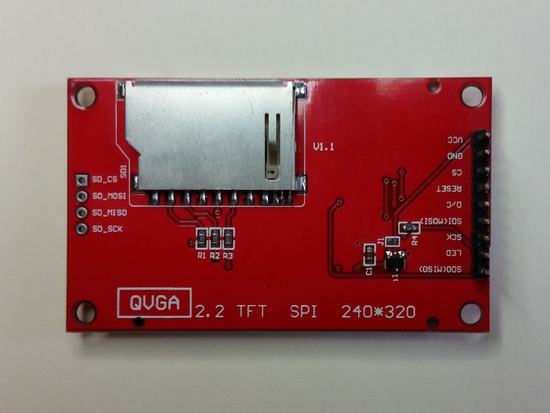
 So, looking at the image left (clicking on it will enlarge the image),
You can see the type of LCD we are talking about.
Dunno why the pin labels are printed upside down but hey-ho.
There is a SD card slot but the pins are not populated.
Maybe I will use that later if things start getting interesting.
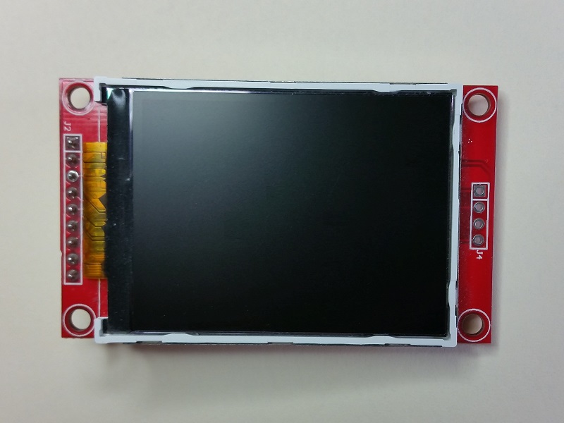
 The front side is pretty simple. There is no touch sensor on this model.
The pins on the top side are not marked,
which is a real pain if you are using it on a breadboard because the pin labels are not visible from the top.
Let's get on connecting it up.
Connections
As previously mentioned, the pin labels are not visible from the front side of the screen.
Referring to the image above, we will designate the top left pin as pin 1.
So to get the code working the way we did, you will need to wire the screen to the Wemos as follows:
| TFT Pin | TFT Pin | Wemos D1 |
|---|---|---|
| Number | Function | Pin Name |
| 1 | VCC | 3.3v |
| 2 | GND | GND |
| 3 | Chip Select | D8 |
| 4 | RESET | RST. See note 1 below |
| 5 | D/C | D3 |
| 6 | MOSI | D7 |
| 7 | SCK | D5 |
| 8 | LED | 3.3v. See note 2 below |
| 9 | MISO | D6. See note 3 below |
Note 1:
It is possible to reset the TFT display by bringing the RESET pin to ground.
This can be controlled within code, using a spare digital pin on the Wemos.
For simplicity, we have tied the TFT RESET pin to the Wemos RST pin.
This means that when we reset the Wemos, for instance, by pressing the reset button, the TFT display is automatically reset too.
Note 2:
This version of the board has a transistor to control the TFT backlight.
It is driven by bringing the TFT LED pin to 3.3v.
Taking this pin to GND, will turn the backlight off.
This could be controlled in code using a spare digital pin on the D1 Mini.
Alternatively, use a PWM pin to control the brightness from code.
For our example, we tied the LED pin to 3.3v, so the backlight is permanently on.
Note 3:
In some cases, we may want to read data from the TFT module, for instance, to read from the frame buffer.
In our example, we are only writing to the TFT screen, not reading from it, so this pin could be left disconnected.
However, since we are using the hardware SPI port on the Wemos D1 already, we may as well connect it. Maybe we will use it later.
LIBRARIES
Have a search around the web for the library named:
TFT_eSPI
We found it at:
https://github.com/Bodmer/TFT_eSPI
Easier still, you can use the Library Manager,
under the Tools menu within the Arduino IDE, to add the library.
As we mentioned earlier, we will not go into the details of how to do this.
We are assuming you already know how, or are able to find out how online.
Tailoring the code
In order to run the TFT screen with our Wemos D1 Mini, using the TFT_eSPI library,
we must make sure the pin designations in the library are the same as those we have connected.
Browse to the folder where the TFT_eSPI library was installed to.
This 'should' be:
Documents/Arduino/libraries/TFT_eSPI/
This will most likely be in the same directory your Arduino IDE saves your project files to.
Next, search within that folder for a file called 'User_Setup.h'
Using your favourite text editor,
open the file and scroll down to the area which looks like this:
// For NodeMCU - use pin numbers in the form PIN_Dx where Dx is the NodeMCU pin designation
#define TFT_CS PIN_D8 // Chip select control pin D8
#define TFT_DC PIN_D3 // Data Command control pin
#define TFT_RST PIN_D4 // Reset pin (could connect to NodeMCU RST, see...
//#define TFT_RST -1 // Set TFT_RST to -1 if the display RESET is connec...
Change those lines to reflect the pins we are using. i.e.
Comment out the third #define and uncomment the fourth, so that it looks like this:
// For NodeMCU - use pin numbers in the form PIN_Dx where Dx is the NodeMCU pin designation
#define TFT_CS PIN_D8 // Chip select control pin D8
#define TFT_DC PIN_D3 // Data Command control pin
//#define TFT_RST PIN_D4 // Reset pin (could connect to NodeMCU RST, see...
#define TFT_RST -1 // Set TFT_RST to -1 if the display RESET is connec...
Next, try running some of the example sketches in the TFT_eSPI 320x240 folder.
Testing
We ran the TFT_graphicstest_PDQ.ino example.
The results are in the video below.
Flying off on another tangent, we used our tft as part of our greenhouse control and monitor project.
>>next>>
